This article is automatically translated from Russian by Google Translator.
Warning! This functionality is in test mode. To use it you need to install a test version of the firmware. We will be glad to get your feedback and suggestions about this functionality. Write to support with a note "Test of working with images in TRIK Studio".
Developing the algorithm under unchanged conditions allows to debug and test it faster, as well as to evaluate and compare the quality of the algorithm and its modifications. This is especially important for computer vision algorithms, when any, even small, camera movement significantly changes the shooting conditions and, as a result, the captured image.
This article will describe how to capture images on the TRIK controller camera, upload this data to a computer and use it in TRIK Studio to develop and debug computer vision algorithms.
ARTag 5x5 datasets
ARTag marker recognition programs can be improved and tested in TRIK Studio on the dataset (see step 3). It includes photos of ARTag 5x5 markers from different angles on a standard TRIK controller camera. The name of each folder in the dataset is the number that is encoded on the ARTag markers that lie in that folder.
Warning! Connect the camera to the "video2" port before turning on the controller.
1. From the controller menu, selectTesting → Camera.
2. The image taken by the camera will be displayed on the screen. It will be saved to the internal memory of the controller.
To take more photos, press the "Exit" (cross) button on the controller and select the Camera menu item again.
1. Connect the TRIK controller to the computer.
2. Enter the IP address of the controller in the address bar of your browser. The TRIK web interface opens.
3. Go to the "Images" tab and click "Download all" to download the image archive.
4. Go to the folder with the downloaded archive and unzip it. Now you can select the images that are best suited for developing and testing the current algorithm.
1. Open the Robot settings in TRIK Studio.
2. In the window that opens, select Robot Model → 2D Model and type in the path to the previously loaded images.
3. Now when you call getPhoto, the images from the specified folder will be loaded sequentially.
An example of a program that sequentially displays images loaded from a specified folder with a 2-second delay.
1. Download the file to your computer or create a new project and copy the code:
2. Run the code in debug mode, using the 2D model as the program execution mode. The controller will display images sequentially on the display.
This article is automatically translated from Russian by Google Translator.
The TRIK controller allows you to build a robotic model without limiting yourself in the choice of "equipment" for it.
It allows you to connect digital and analog sensors, external devices via i2c and UART protocols, has two video ports and a USB connector.
There are 6 ports for servo motors and 4 ports for power motors.
This section contains information on how to connect sensors, motors, cameras to the TRIK controller - it describes the process of testing the connected devices, their configuration, and effective use together with the TRIK Studio programming environment.
This article is automatically translated from Russian by Google Translator.
Both video modules and USB webcams can be connected to the TRIK controller.
Video module
USB webcam
The video module connects to the video1 or video2 port, the USB webcam connects to the USB port.
Connect the video module to the video2 (or video1) port so that the red plug pin is on the right.
The camera in TRIK Studio can be run in three modes:
As a line sensor.
As objects sensor.
As a color sensor.
Write an algorithm to initialize the video camera:
After the camera is initialized, a video broadcast with additional graphic elements will appear on the display.
Warning! By default, the Line Sensor mode will be enabled. To change the mode of use, go to the properties of the "Initialize Camera" block and change the mode to the desired one.
The camera as a line sensor is needed to solve the problem of driving on the line, as well as on a discontinuous line.
In order to enable the camera as a line sensor, you must change the camera mode in the "Initialize Camera" block properties, to Line Sensor. The Line Sensor mode has a lineSensor variable.
Task. Write an algorithm for moving the robot along a line using a camera.
1. Initialize the variable k - the proportionality factor to be used in the proportional regulator for the robot's motion.
2. Initialize the camera as a line sensor.
Warning! The "Wait for button to be pressed" block is necessary so that the camera has time to turn on. When the image from the camera appears on the robot's screen, you can proceed to the next step.
3. Detect the camera on the object.
4. Write a controller for motion. Use the "Line Sensor to Variable" block, which writes a reading of the object's deviation from the center of the screen along the X-axis (from -100 to 100) to a variable specified in the properties. In other words, it is a dynamic error.
1. Run the program on the robot.
2. Wait for the camera to turn on.
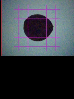
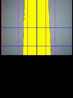
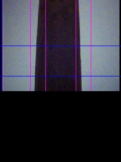
3. In Line Sensor mode, the screen will display 4 purple guides. Aim the camera at the line so that the right edge of the line falls in the corridor between the two right guides and the left edge between the two left guides.
4. Press the Up button on the controller to detect an object (line).
Note that the video is streamed to the screen in 240×140 px format, which is exactly half of the screen.
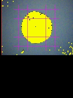
The line must fill with yellow dots, as in the picture, to know that detection has occurred:
5. Press the Down button.
The camera as an object sensor is required for object recognition and tracking tasks. In order to enable the camera as a line sensor, you must change the camera mode, in the properties of the "Initialize Camera" block, to Object Sensor. The Object Sensor mode has sensor variables: objectSensorSize, objectSensorX, objectSensorY.
Task. Write an algorithm for object recognition using a camera.
Attention! The robot must output to the console the coordinates of the object center and its diameter in pixels.
1. Initialize the camera as an object sensor.
Warning! The "Wait for the button to be pressed" block is necessary so that the camera has time to turn on. When the camera image appears on the robot's screen, you can proceed to the next step.
2. Detect the camera on the object.
3. Write a loop with a condition to exit the program by pressing Esc on a false branch.
4. On the true branch, add a function to assign the coordinates of the center of the object and the diameter in pixels, to the variables a, b, c.
5. Next, add the variables a, b, c to the console and end the loop with the "Timer" block:
1. Run the program on the robot.
2. Wait for the video camera to turn on.
3. Position the robot so that the camera is facing a small square on the object. Press the Up button on the controller to detect the object.
To understand that detection has occurred, the object must fill with yellow dots, as in the picture:
4. Press the Down button on the controller.
The camera as a color sensor is necessary for color recognition tasks.
In order to enable the camera as a line sensor, you must change the camera mode, in the properties of the "Initialize Camera" block to Color Sensor.
Color Sensor mode has sensor variables of three colors (red, green, blue): colorSensorR, colorSensorG, colorSensorB.
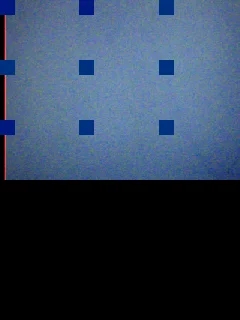
In Color Sensor mode, the camera divides the frame into 9 zones and returns the average color value of the center zone.
Write an algorithm for recognizing green and red using a camera. The robot should output to the console the color it sees.
Note that the problem can only be solved on a real robot.
1. Initialize the camera as a color sensor.
Warning! The "Wait for button to be pressed" block is necessary so that the camera has time to turn on. When the camera image appears on the robot's screen, you can proceed to the next step.
2. Add the function of assigning touch variables to variables a, b.
3. Write a condition that will distinguish between red and green. Given that red is colorSensorR = 255 , and green is colorSensorG = 255 .
1. Execute the program on the robot. 2. Wait for the video camera to turn on. 3. Position the robot so that the camera is pointing at the color you want to recognize.
4. Press the Up button on the controller to start color recognition. The robot should display the color the camera is pointing at (Green, Red).
This article is automatically translated from Russian by Google Translator.
The following describes how to set up the USB camera in lineSensor mode.
To work with the USB camera, you must change the path to the script in the system-config.xml file on the TRIK controller.
This can be done with either of the two utilities:
.
.
1. to the controller using "Wi-Fi Access Point" or "Wi-Fi Client" mode.
2. Open .
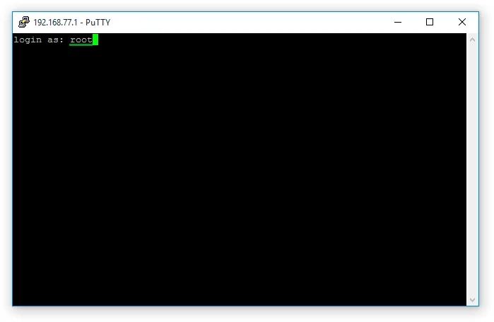
3. Launch the PuTTY utility. To do this, from the main menu, open Tools → External tools → PuTTY.
5. In the window that appears, enter root. Leave the "Password" field blank.
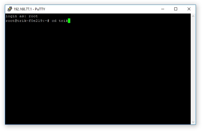
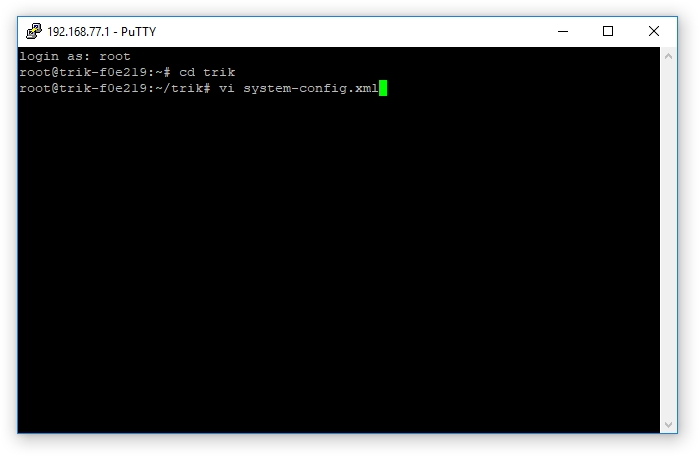
6. Enter the command cd trik to navigate to the corresponding directory
7. Use the vi editor to edit the file. To run it, type vi system-config.xml.
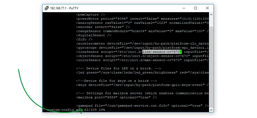
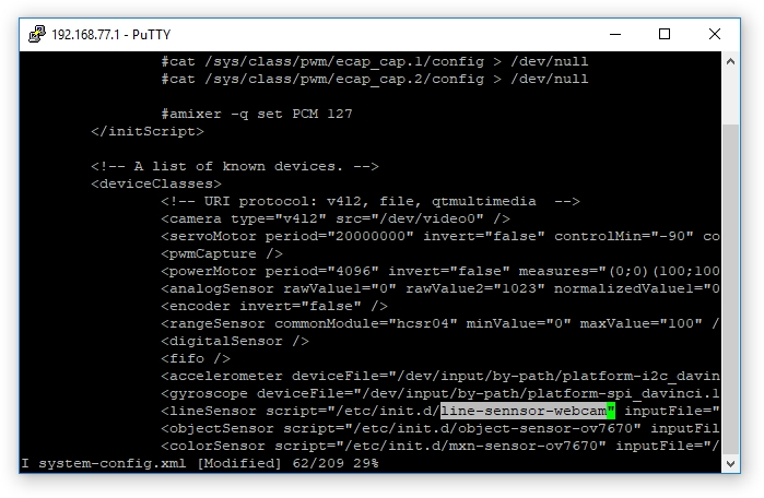
8. Use the arrow keys on your keyboard to move to line 62.
9. Press i to edit, find the script name line-sensor-ov7670 and correct it to line-sensor-webcam.
10. To exit edit mode, press "Esc".
11. Enter the command :wq and press "Enter" to save and exit the vi editor.
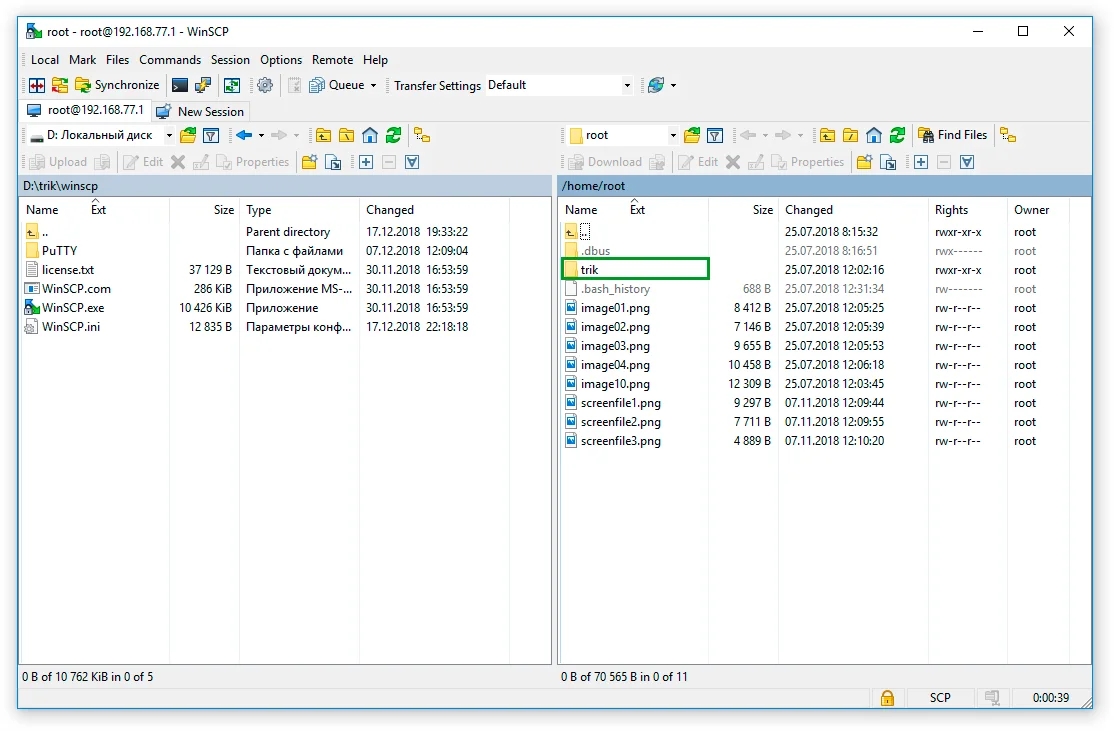
1. In the directory with the installed TRIK Studio, go to the winscp folder and run WinSCP.exe.
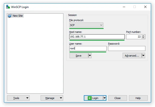
2. Fill in the data:
File protocol: SCP.
User name: root.
Leave the "Password" field blank.
3. Press the "Login" button.
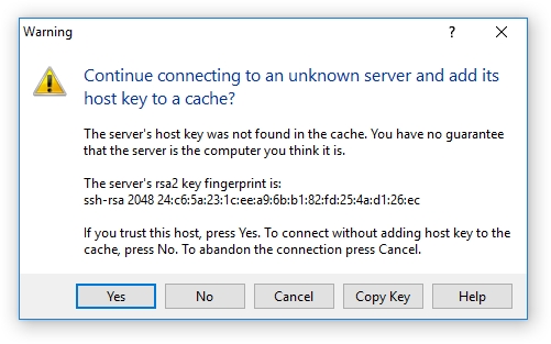
4. If the "Warning" window appears, click "Yes".
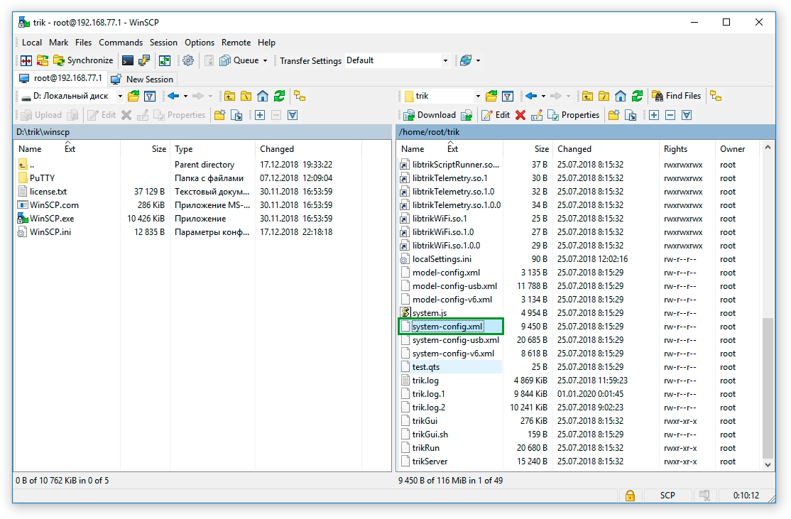
5. Navigate to the trik folder.
6. Find and open the system-config.xml file.
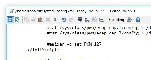
7. On line 62 of the file that opens, find the name of the script line-sensor-ov7670 and correct it to line-sensor-webcam.
8. Save your changes by pressing Ctrl+S or the "floppy" icon in the upper left corner, and close the editor.
This article is automatically translated from Russian by Google Translator.
On the TRIK controller you can test the devices connected to it:
Analog sensors
Servo motors
Power motors
Digital sensors
Encoders
Gyroscope
Accelerometer
Camera
To do this, go to the Test menu.
Warning! The device must first be connected to a specific port to test it. To test the device, you must first connect it to a specific port.
To start testing analog sensors, select the corresponding item in the list.
1. To start a servo test, select the corresponding item in the list.
2. Select the port to which the servo drive is connected. The servo drives are connected to ports S1-S3.
3. Press the "Enter" button on the controller to apply power to the servo drive.
4. If you add power with the "Right" button, the servo will rotate clockwise.
5. If you turn it down, it's counterclockwise.
1. To start the power motor test, select the corresponding item in the list.
2. Select the port to which the motor is connected. The motors are connected to ports M1-M4.
3. Press the "Enter" button on the controller to apply power to the motor.
4. If you add power with the "Right" button, the motors will spin forward.
5. If you turn it down, back up.
Warning! If the motor rotates in the wrong direction, just change the direction of the current, disconnect the power wire and insert the other side.
To start testing digital sensors, select the corresponding item in the list.
Warning! If the sensor reads -1, then it is either too far away from the object or too close to it.
1. To start the encoder test, select the corresponding item in the list.
2. Connect the wheels to the motors with a bushing.
3. To test the performance of the encoder, rotate the wheel back and forth and watch the encoder readings change.
Warning! Encoders are incremental. When scrolling the motor the encoder value can be either negative or positive.
1. To start the gyroscope test, select the corresponding item in the list.
2. To test the performance of the gyroscope, change the position of the robot in space and see if the readings change.
Warning! All readings are in milligrades.
1. To start the gyroscope test, select the corresponding item in the list.
2. To test the performance of the accelerometer, change the position of the robot in space and see if the readings change.
Warning! All readings are in milligrades.
If the camera is working properly, it should display an image on the screen.
4. Enter the (specified in the network parameters of the controller) and click "Open".
Host name — .
Port
Configuration
A1–A2
Infrared distance sensor.
Value limits: 8-80 cm.
A3–A4
Touch sensor. Values:
0 - no touch,
1 - pressing.
A5–A6
Light sensor.
Value limits: 0-100. 0 - white, 100 - black.
The sensor must be installed at a distance of 8-15 mm from the surface.
Port
Configuration
D1–D2
Ultrasonic distance sensor.
Value limits: 8-250 cm.

This article is automatically translated from Russian by Google Translator.
The TRIK controller is supplied with power:
1. Power supply with 12V output voltage and 2A output current or 12V 5A power supply (depending on the set).
2. Three-cell lithium polymer battery (LiPo) with a voltage of 12.6 V and a capacity of 2200 mAh or 4200 mAh.
The battery used has two connectors:
1. Specific two-pin with power wires to connect to the controller.
2. Four-pin for connection to a dedicated battery charger with balancer.
Only use dedicated battery chargers to charge the batteries.
Observe the condition of the battery while it is being charged. If the cells appear to be blistering, immediately disconnect the battery from the charger and move it to a fireproof cover. Do not resume the charging process of a faulty battery.
Short-circuiting causes a rapid discharge, with currents in excess of those permitted, which can cause battery failure, fire, and severe burns. Do not short-circuit batteries or cells.
Do not store batteries in direct sunlight.
Do not allow the voltage to drop below 3.2 V per battery cell. Deep discharge causes permanent damage to the battery and poses a risk of fire.
When storing the battery for a long time (more than a week), the voltage per battery cell must be in the range of 3.7-3.87 V. Failure to observe this condition will significantly reduce battery life.
Do not expose the battery to heat, including self-heating above 45°C. If the battery is hotter than 45°C, allow it to cool to room temperature before use or charging.
Protect the battery from mechanical damage. If a shock occurs, carefully inspect the battery on a refractory surface. Continue to use the battery only when you are absolutely certain that there is no damage.
If the balancer is missing or not used, if the charge voltage or current is exceeded, or if any of the battery cells are overcharged, the battery may not only fail but also self-ignite.
To charge LiPo batteries, only use a dedicated microprocessor-based battery charger with a complex charge cycle and built-in balancer.
Carefully inspect the battery before you begin charging it.
Charge batteries on a fireproof surface.
Allow the battery to cool to ambient temperature before beginning the charging process.
It is recommended to monitor the temperature of the battery during charging. A temperature over 40-50°C indicates that something is wrong or the battery is ruined. Disconnect the battery from the charger immediately.
Dispose of lithium polymer batteries at a specialized company in your community.
Lithium polymer batteries are environmentally friendly. For safety reasons, however, lithium polymer batteries should be fully discharged before disposal.
If the battery is physically damaged (inflated, split, etc.) it should not be discharged. Go directly to point 5 below.
Make sure that the battery is not hot (above ambient temperature).
Place the battery in a fireproof container or bucket of sand.
Connect the battery to the battery arrester. Set the discharge voltage to the lowest possible value.
Discharge the battery until its voltage reaches 1 V or lower.
Prepare a plastic container (do not use metal) with cold water and mix 1/2 cup salt per liter of water. Leave the battery in the saltwater container for at least 2 weeks.
Take the battery out of the saltwater and wrap it in newspaper or paper towels.
Dispose of regular garbage.
